REQ 308231 Airlink Requirements
![]()
Air Link
Air Link eSERV Requirements
CALIDUS eSERV
16th April 2013 - 0.1
Reference: REQ 308231
Contents
Introduction
This document is the Air Link eSERV Requirements.
Objective
The primary purpose of this document is to document the requirements gathered from Air Link, on 11/04/2013, at the Air Link site.
This document has been written in a manner such that it can be approved by non-technical representatives of Air Link whilst also being of sufficient detail to allow the Functional or Technical Specification phase for this area to begin.
Scope and Limitations
This document is based on the documentation provided by Air Link, as referred to in the appendices, as well as information gleaned from site visits and workshops with Air Link.
- The changes will be made in the latest version of the CALIDUS eSERV system.
- Although the document describes all changes discussed with the client, subsequent meetings have marked several changes as out of scope. Although these are referred to in several places throughout the document to identify the ideal process, if the initial change is marked out of scope, all references to it are also out of scope.
- SLA display (RAG Colouration)
- Maintenance Jobs
- Linked Product to System Type
- Reports
Client Requirements
Listed below are the proposed processes that will be followed by the operatives using CALIDUS eSERV. Also shown are the SCRs required for this to be achieved.
System Administration
The CALIDUS eSERV system is configured and administered through a web Admin system. This is fully documented elsewhere. Certain elements will be modified as part of these changes to ensure that the system can be configured correctly for the customer's use.
The Job Group and Site screens will be modified to allow the system to be configured for:
- Job Suspension
- Optional Document Photo
- Configuration of new Service Report format
- Configuration of customer-specific Info tab.
The Job Details screen will be modified to allow the user to:
- create Service jobs
- specify a Service ID
- specify a Service Group (e.g. Checkout, Cash Tube, etc)
The Service Details screen will be modified to:
- Change labels and remove unwanted items (e.g. VNOS)
- Add System Type and Job Status
| SCR-308231-1: | Add new Configuration Options to Job Group and Site. |
| SCR-308231-2: | Custom style to change labels and hide unwanted elements. |
| SCR-308231-3: | Add new elements to Job Details and Service Details screens. |
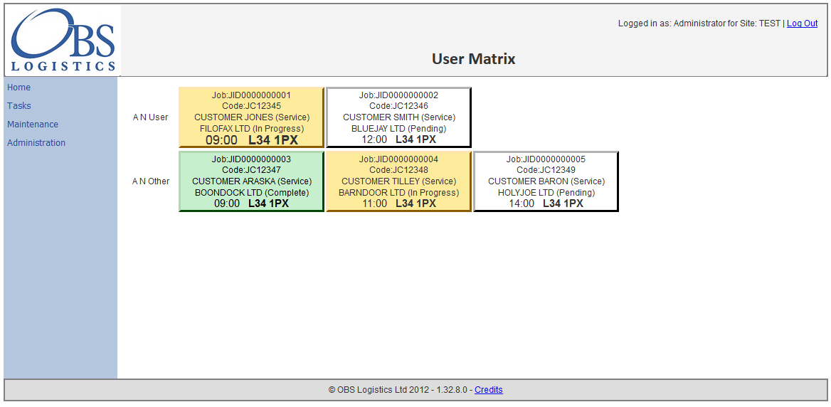
![]() Warning: As a potential addition, charged separately, a new screen will be added to the Tasks menu, labelled as User Matrix.
Warning: As a potential addition, charged separately, a new screen will be added to the Tasks menu, labelled as User Matrix.
| SCR-308231-4: | Add new User Matrix screen. |
This screen will list all users on the chosen site down the left and show the current tasks assigned to them, in date/time sequence. A full estimate and specification of this new screen is expected to be entered into, but a prototype layout and functionality guideline follows.
- The screen will allow the user to filter by User IDs
- The first column will show the user name.
- All subsequent columns will show the jobs assigned.
- The Job cells will show details of the job, content and layout to be defined later. Such items may be:
- Service ID or Code
- Customer Name
- Contact Name
- Post Code
- Planned Time
- Job Type
- Status
- Clicking on the Job cell will take the user to the existing Job screen, showing only the job selected.
Creating Calls
Calls can be created using the Jobs screen from the menu.
The use of this screen is described in the Admin User Guide. In summary:
- Click the New button to create a new call, and enter the details in the pop-up screen. Click Save when finished.
- Existing calls can be found using the Find button and entering seelction criteria, then clicking Search.
- Editable fields against calls can be seen by clicking Select - the call can be amended, deleted, cancelled and saved from this pop-up screen.
- The user-entered details of a call can be checked by clicking the Details button.
Assigning Calls
Only when a user has a load (work list) assigned to them will they be able to complete calls.
To create a load, use the Loads screen from the menu.
The use of this screen is described in the Admin User Guide. In summary:
- Click the New button to create a new Load, and enter the details in the pop-up screen. Click Save when finished.
- Existing loads can be found using the Find button and entering seelction criteria, then clicking Search.
- Editable fields against loads can be seen by clicking Select - the load can be amended, deleted, cancelled and saved from this pop-up screen.
- The calls assigned to a load can be seen by clicking the Details button - this will display the Jobs screen above.
Calls can be assigned to a load in two ways:
- Singly through the Jobs screen, by setting the Load aganst the call when created or edited.
- Mass entry through the Loads screen, by finding a load, clicking Details, then clicking the Assign button and assigning multiple calls, then clicking the Assign button.
Loads can be assigned and unassigned to users in two ways:
- Singly in the Loads screen, by setting the user against the load when created or edited.
- Mass entry in the Users Screen, by finding the User, clicking Loads and using the Load Assignment screen to Assign or Unassign loads.
![]() Note: Multiple work lists can be assigned to a user - they will be given to the user to complete in sequence.
Note: Multiple work lists can be assigned to a user - they will be given to the user to complete in sequence.
Logging On
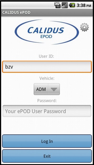
The engineer should enter the User ID, Vehicle and Password that they have been provided. If there is any error regarding the values entered, the application will inform you of the error. A pop-up keyboard will be displayed for entry of the details.
A Settings button is provided to configure the device through a Configuration screen. ![]() Note: If the device has never been configured before, this screen will prompt the user to configure the system first.
Note: If the device has never been configured before, this screen will prompt the user to configure the system first.
If the user has a data connection (Wireless or Mobile), the unit will download all of the latest configuration data from the server, and a load to be completed.
If the vehicle being used has not been checked recently, the unit will direct the engineer to complete Vehicle Checks, if configured.
If no load has been assigned to the user, the unit will display a message and ask if they want to recheck.
If a Load has been assigned to the user, they will be directed to the Job List screen.
Job List
Upon logging onto a device, the user will be presented with a work list (Load) of Calls to complete.
The Calls on the Job List will be sorted in Start Planned Date and Time sequence.
The application periodically checks to see if there have been any updates to the work list - if so, the screen will display a summary of the changes and advise the user to check the jobs before accepting the changes. This auto-update can be forced from the menu on the application on this screen.
Already Completed or Cancelled jobs can be shown or hidden by pressing the Menu button on the device and toggling between Show All Jobs and Show Outstanding Jobs.
Job Details
The engineer will select the Call to be progressed from the Job List.
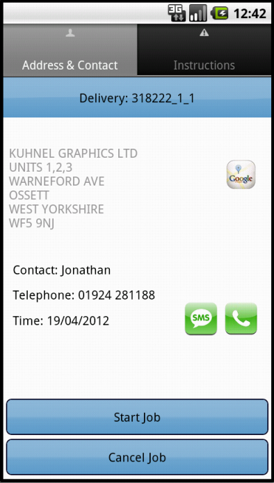
When selected, the system will display the Job Summary screen.
The user can then start the Call, by clicking on the Start button - this marks the Call as in progress, and captures the Actual Call Start time. The button will change to a label of Arrive Job
![]() Note: All Job Status information similar to this will be sent back to the server immediately, to ensure that the server has the best information available as quickly as possible.
Note: All Job Status information similar to this will be sent back to the server immediately, to ensure that the server has the best information available as quickly as possible.
The user will at this time drive to the site, and can use the contact or navigation options provided within the application. ![]() Note: Telephoning or texting the customer will only be allowed if the device's SIM has a Voice plan.
Note: Telephoning or texting the customer will only be allowed if the device's SIM has a Voice plan.
When the engineer arrives at the site, the Arrive button is clicked, which does the following:
- the PDA Call Arrival Date and Time will be updated on the server
- the screens required to process the Service Call will be shown.
The user also has the facility to Cancel a job from this screen, using the Cancel button.
Service Call Type Process
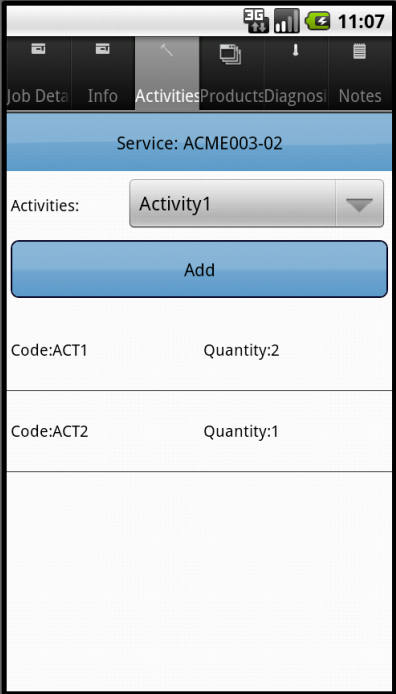
Service Calls will be configured to display the following tabs:
- Job Details
- Info
- Products
- Diagnosis
Job Details Tab
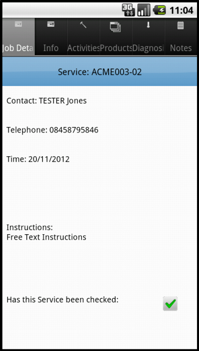
This tab displays:
- Contact name
- Telephone
- Planned Date/Time
- Instructions - the reported fault.
It is not expected that any information needs to be added to this screen at this time.
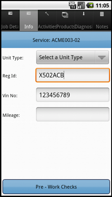
Info Tab
This tab currently contains the job-level information required for the Service.
This screen will be modified to display a picker for System Type.
| SCR-308231-5: | Add System Type to Info tab. |
The actual values in here are controlled by the system set-up of the Product Groups in the Admin system. It will be required that this is entered.
Products
This tab allows entry of Installed and Removed Products, during the completion of the call.
If a product is used during the call, select the product from the picker and click the Installed button.
If a product is removed during the call, select the product from the picker and click the Removed button.
If more than one of any product is used or removed during the course of the job, simply add as many times are required, and the quantity will be increased.
The user can long-press on a product line to:
- Remove 1
- Remove All.
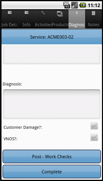
Diagnosis Tab
This tab allows the user to enter Problem Diagnosis information.
This screen will be modified to:
- Add Job Status, a picker with 'Complete' and 'Suspended'. A value must be selected.
- Relabel 'Customer Damage' as 'Misuse'.
- Remove VNOS flag
| SCR-308231-6: | Add Job Status to Diagnosis tab. |
| SCR-308231-7: | Custom style the client to change labels and hide unwanted elements. |
A Diagnosis and a Job Status must be entered.
Service Call Confirmation
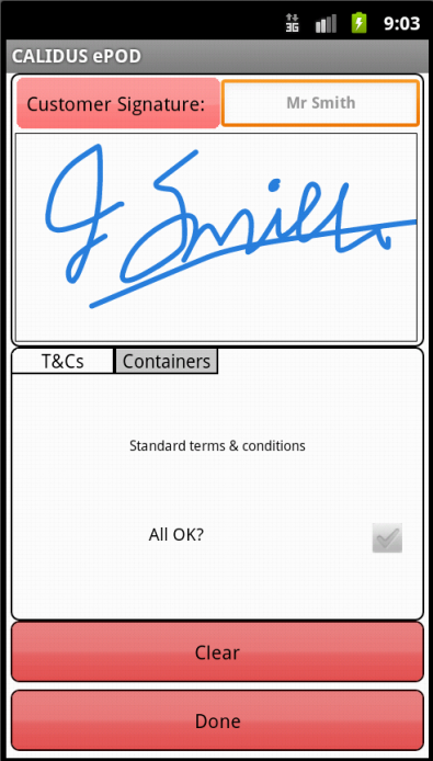
Once all the information has been entered and the engineer clicks the Complete button, the PDA will prompt for the customer's signature.
Once entered, the PDA will require the entry of Engineer signature.
When complete and confirmed, the device will ask the user whether any job photos are required. If so, the device will display the Job Photo prompt, where the user will be able to take an image and associate it to the job.
| SCR-308231-8: | Allow optional Photo on finishing Job. |
![]() Note: The existing functionality in the system to deal with this Imaging is referred to as Document Photo. This will be modified to so that the labels and messages shown on the PDA refer to Job Photo instead, as part of the customer styling.
Note: The existing functionality in the system to deal with this Imaging is referred to as Document Photo. This will be modified to so that the labels and messages shown on the PDA refer to Job Photo instead, as part of the customer styling.
Once all information is entered, the user will be returned to the Job List screen. The completed job will be removed from the list. The completed job will be transferred back to the main system with all the details, signatures and photos.
Already Completed or Cancelled jobs can be shown or hidden by pressing the Menu button on the device and toggling between Show All Jobs and Show Outstanding Jobs.
In the event that a job has been postponed, the system will be modified to create a new copy of the job, with a new ID. All information from the old job will be copied over, minus the Diagnosis and Products information.
| SCR-308231-9: | On Job Suspension, create an unassigned copy of the job. |
Log-off System
A user can choose to exit the system at any time, by clicking Exit from the Job List screen, or pressing the device Back button. If they do, they will be prompted to confirm.
If there is any unsent information at this time, the unit will keep attempting to send the information before it exits.
Service Report
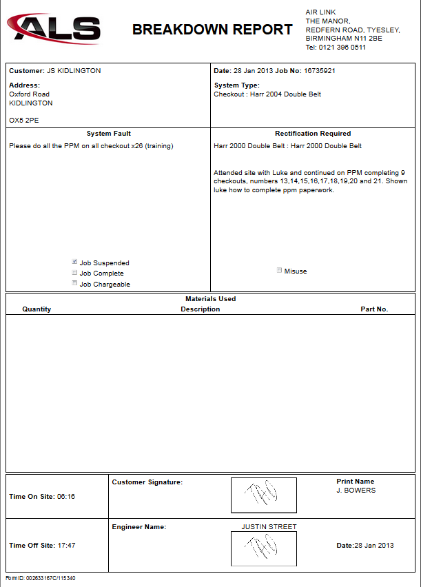
A new Service Report format will be written for the operation, based on the existing Breakdown Report. The format has been prototyped and is shown below.
![]() Note: The printing of the report is browser-dependent and can differ in small ways from the sample above.
Note: The printing of the report is browser-dependent and can differ in small ways from the sample above.
| SCR-308231-10: | New Service Report format. |
Appendix A: Table of SCRs
| SCR# | System | Area | Description | Estimate (Days) | Notes |
| 1 | eSERV | Admin | Add new Configuration Options to Job Group and Site. | N/A | |
| 2 | eSERV | Admin | Custom style to change labels and hide unwanted elements. | N/A | |
| 3 | eSERV | Admin | Add new elements to Job Details and Service Details screens. | N/A | |
| 4 | eSERV | Admin | Add new User Matrix screen. | 6,069.00 | 1 |
| 5 | eSERV | PDA | Add System Type to Info tab. | N/A | |
| 6 | eSERV | PDA | Add Job Status to Diagnosis tab. | N/A | |
| 7 | eSERV | PDA | Custom style the client to change labels and hide unwanted elements. | N/A | |
| 8 | eSERV | PDA | Allow optional Photo on finishing Job. | N/A | |
| 9 | eSERV | Server | On Job Suspension, create an unassigned copy of the job. | N/A | |
| 10 | eSERV | Admin | New Service Report format. | N/A |
Notes:
- All ballpark costs in this document are provided as-is, are legally non-binding and subject to raising a formal change request with OBS Logistics.
Appendix B: Document References
B.1 References
| Ref No | Document Title & ID | Version | Date |
| 1 | UG 291094 EPOD Admin User Guide | 2.0 | 4/4/2012 |
| 2 | UG 291097 EPOD Client User Guide | 2.0 | 4/4/2012 |
B.2 Glossary
| Term | Definition |
|---|---|
| EPOD | Electronic Proof of Delivery. The OBS EPOD system is CALIDUS ePOD. |
| CALIDUS eSERV | The OBS mobile system to complete Service functionality in the field. This is part of the CALIDUS ePOD system. |
| PDA | The mobile device on which the C-ePOD system will run in the field. This can be a Phone, EDA or industrial PDA, running Android. |
| DAL | Data Access Layer. A mechanism for accessing data by the system that is removed from the application, allowing for simplified access and providing protection to the data, as only approved DAL methods can be used to modify it. |
| GPS | Global Positioning System. A mechanism of retrieving accurate positioning information in the form of Latitude and Longitude (Lat-Long) co-ordinates from a device. |
| GPRS, 3G, HSDPA, Data Service | All terms referring to mobile device network connectivity, and the speed at which the device connects to the internet. |
B.3 Authorised By
Jamie Foster | OBS Project Manager | _____________________________ |
